
Dual-tone multi-frequency signaling (DTMF) is a telecom signaling system using the voice-frequency band over telephone lines between telephone and other comn. devices and switching centers. DTMF was first developed in the Bell System in the United States, and became known under the trademark Touch-Tone for use in push-button telephones supplied to telephone customers, starting in 1963. DTMF is standardized as ITU-T Recommendation Q.23. It is also known in the UK as MF4. The Touch-Tone system using a telephone keypad gradually replaced the use of rotary dial and has become the industry standard for landline and mobile service. Other multi-frequency systems are used for internal signaling within the telephone network.
Multi-frequency signaling (MF) is a group of signaling methods that use a mixture of two pure tone (pure sine wave) sounds. Various MF signaling protocols were devised by the Bell System and CCITT. The earliest of these were for in-band signaling between switching centers, where long-distance telephone operators used a 16-digit keypad to input the next portion of the destination telephone number in order to contact the next downstream long-distance telephone operator. This semi-automated signaling and switching proved successful in both speed and cost effectiveness. Based on this prior success with using MF by specialists to establish long-distance telephone calls, dual-tone multi-frequency signaling was developed for end-user signaling without the assistance of operators.
The DTMF system uses a set of eight audio frequencies transmitted in pairs to represent 16 signals, represented by the ten digits, the letters A to D, and the symbols # and *. As the signals are audible tones in the voice frequency range, they can be transmitted through electrical repeaters and amplifiers, and over radio and microwave links, thus eliminating the need for intermediate operators on long-distance circuits.
The DTMF telephone keypad is laid out as a matrix of push buttons in which each row represents the low frequency component and each column represents the high frequency component of the DTMF signal. The commonly used keypad has four rows and three columns, but a fourth column is present for some applications. Pressing a key sends a combination of the row and column frequencies. For example, the 1 key produces a superimposition of a 697 Hz low tone and a 1209 Hz high tone. Initial push-button designs employed levers, enabling each button to activate one row and one column contact. The tones are decoded by the switching center to determine the keys pressed by the user.
| 1209 Hz | 1336 Hz | 1477 Hz | 1633 Hz | |
|---|---|---|---|---|
| 697 Hz | 1 | 2 | 3 | A |
| 770 Hz | 4 | 5 | 6 | B |
| 852 Hz | 7 | 8 | 9 | C |
| 941 Hz | * | 0 | # | D |
DTMF was originally decoded by tuned filter banks. By the end of the 20th century, digital signal processing became the predominant technology for decoding. DTMF decoding algorithms typically use the Goertzel algorithm. As DTMF signaling is often transmitted in-band with voice or other audio signals present simultaneously, the DTMF signal definition includes strict limits for timing (minimum duration and inter-digit spacing), frequency deviations, harmonics, and amplitude relation of the two components with respect to each other (twist).
The MT8870D/MT8870D-1 is a complete DTMF receiver integrating both the band-split filter and digital decoder functions. The filter section uses switched capacitor techniques for high and low group filters; the decoder uses digital counting techniques to detect and decode all 16 DTMF tone pairs into a 4-bit code. External component count is minimized by on chip provision of a differential input amplifier, clock oscillator and latched three-state bus interface. SSI202 and M957 are alternatives for MT8870 but they are no longer in production.
Features of MT8870D IC :
- Complete DTMF Receiver
- Low power consumption
- Internal gain setting amplifier
- Adjustable guard time
- Central office quality
- Power-down mode
- Inhibit mode
- Backward compatible with MT8870C/MT8870C-1
Applications of MT8870D :
- Receiver system for British Telecom (BT) or CEPT Spec (MT8870D-1)
- Paging systems
- Repeater systems/mobile radio
- Credit card systems
- Remote control
- Personal computers
- Telephone answering machine
| Digit | TOE | INH | ESt | Q4 | Q3 | Q2 | Q1 |
|---|---|---|---|---|---|---|---|
| ANY | L | X | H | Z | Z | Z | Z |
| 1 | H | X | H | 0 | 0 | 0 | 1 |
| 2 | H | X | H | 0 | 0 | 1 | 0 |
| 3 | H | X | H | 0 | 0 | 1 | 1 |
| 4 | H | X | H | 0 | 1 | 0 | 0 |
| 5 | H | X | H | 0 | 1 | 0 | 1 |
| 6 | H | X | H | 0 | 1 | 1 | 0 |
| 7 | H | X | H | 0 | 1 | 1 | 1 |
| 8 | H | X | H | 1 | 0 | 0 | 0 |
| 9 | H | X | H | 1 | 0 | 0 | 1 |
| 0 | H | X | H | 1 | 0 | 1 | 0 |
| * | H | X | H | 1 | 0 | 1 | 1 |
| # | H | X | H | 1 | 1 | 0 | 0 |
| A | H | L | H | 1 | 1 | 0 | 1 |
| B | H | L | H | 1 | 1 | 1 | 0 |
| C | H | L | H | 1 | 1 | 1 | 1 |
| D | H | L | H | 0 | 0 | 0 | 0 |
| A | H | H | L | Undetected, the output code will remain the same as the previous detected code | |||
| B | H | H | L | ||||
| C | H | H | L | ||||
| D | H | H | L | ||||
Functional Decode Table
(L=Logic Low, H=Logic High, Z=High Impedance, X = Don’t care)
More detail about MT8870 IC is available in datasheet, click here to download it.
MT8870 DTMF Decoder module schematic

Features of MT8870 DTMF Decoder Module :
- Power Input: +5VDC (+4.5V to +5.5V)
- Onboard 3.5 mm jack input
- MT8870 Based Frequency Decoder
- 5 Channel Interface
- Detects 0-9, A-D, *, #
- LED indication for binary output state
- 2.54” Pin pitch
- Board Dimension: 37 x 25 x 12 mm (l x w x h)
MT8870 Module interface with Arduino
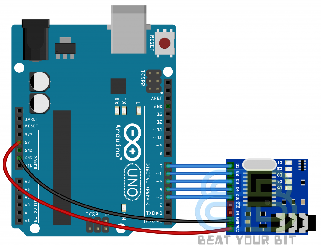
Configuration is as simple as shown in above diagram. To give DTMF input, you can connect AUX cable from MT8870 module 3.5 mm jack to your phone’s 3.5 mm jack.
Arduino code for MT8870 module
|
1 2 3 4 5 6 7 8 9 10 11 12 13 14 15 16 17 18 19 20 21 22 23 24 25 26 27 28 29 30 31 32 33 34 35 36 37 38 39 40 41 42 43 44 45 46 47 48 49 50 51 52 53 54 55 56 57 58 |
void setup() { Serial.begin(9600); pinMode(3, INPUT); pinMode(4, INPUT); pinMode(5, INPUT); pinMode(6, INPUT); pinMode(7, INPUT); } void loop() { uint8_t number; bool signal ; signal = digitalRead(3); if(signal == HIGH) /* When DTMF tone is detected,STQ will read HIGH for the duration of the tone */ { delay(250); number = ( 0x00 | (digitalRead(7)<<0) | (digitalRead(6)<<1) | (digitalRead(5)<<2) | (digitalRead(4)<<3) ); switch (number) { case 0x01: Serial.println("Pin Pressed : 1"); break; case 0x02: Serial.println("Pin Pressed : 2"); break; case 0x03: Serial.println("Pin Pressed : 3"); break; case 0x04: Serial.println("Pin Pressed : 4"); break; case 0x05: Serial.println("Pin Pressed : 5"); break; case 0x06: Serial.println("Pin Pressed : 6"); break; case 7: Serial.println("Pin Pressed : 7"); break; case 0x08: Serial.println("Pin Pressed : 8"); break; case 0x09: Serial.println("Pin Pressed : 9"); break; case 0x0A: Serial.println("Pin Pressed : 0"); break; case 0x0B: Serial.println("Pin Pressed : *"); break; case 0x0C: Serial.println("Pin Pressed : #"); break; } } } |
You can download above sketch from here.
For DTMF signal input to the module, you have to connect MT8870 module and your phone using 3.5mm audio jack AUX cable.

Now open the dial pad of you phone, press 0 to 9, * & # numbers and you will see the output LEDs on module will change their state & you will observe in serial module that which key is pressed.

I hope you will learn to use MT8870 DTMF decoder module by this tutorial & it will be helpful to add GSM control in your DIY stuff. In further of this tutorial, you can add some logical conditions in code to turn on-off Arduino GPIO by particular DTMF tone received and same can be designed as device control using phone. In future such projects will be uploaded in #BeatYourBit website. If you like this tutorial, share it with your friends & any Arduino newbie you know. Give your feedback about this tutorial in Contact, Your feedback will be appreciated.
Like/Follow @beatyourbit on Facebook, Twitter, Instagram & Telegram for latest updates.